1. Test Tools and Basic Communication Parameters
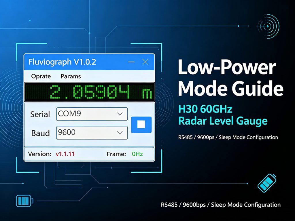
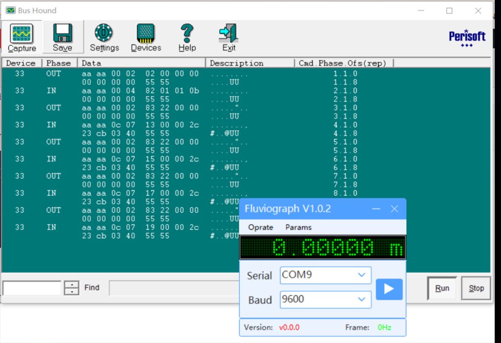
Test Program: Fluviograph.exe [V1.0.2]
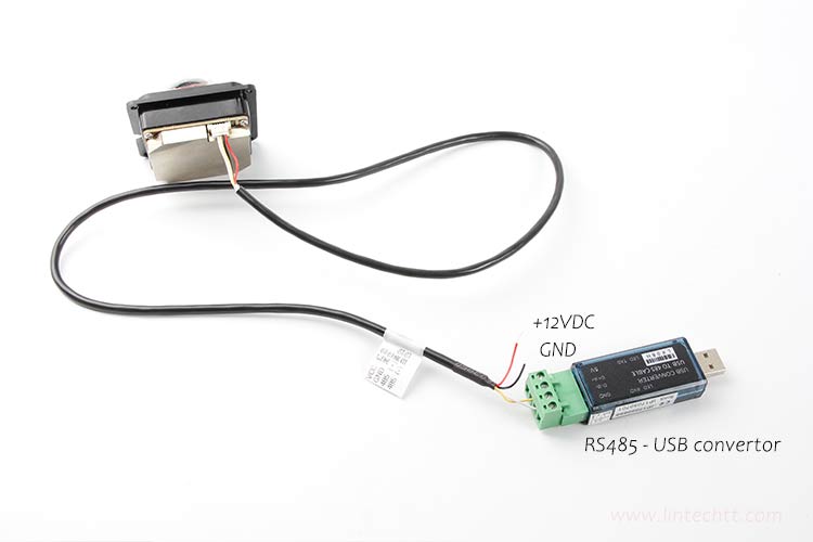
Communication settings: RS485 protocol, baud rate 9600 bps
Operation: Select the corresponding COM port and click the Run button.
Raw commands sent by the software can be captured via a COM‑port monitor tool:
- Port reopen command:
42 5a 30 31 54 30 31 30 30 - Command for requesting real‑time radar detection data:
aa aa 00 02 02 00 00 00 00 00 00 00 55 55
Note: One set of detection data will be returned by the device upon each transmission of this command.
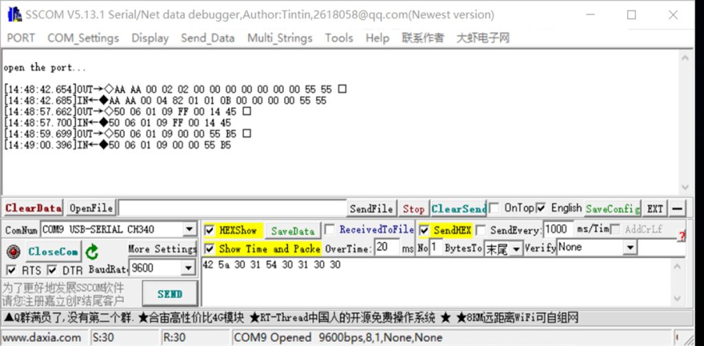
Verification with SSCOM Serial Debug Tool
- Select the target COM port, set baud rate to 9600 bps, and click
OpenCOMto open the serial port. - Switch to HEX sending mode and send the following commands:
42 5a 30 31 54 30 31 30 30— send onceaa aa 00 02 02 00 00 00 00 00 00 00 55 55— send for every data query
Normal‑mode communication example:
Host Send (OUT):
AA AA 00 02 02 00 00 00 00 00 00 00 55 55Sensor Reply (IN):
AA AA 00 04 82 01 01 0B 00 00 00 00 55 55
The above message indicates the radar is running in normal operating mode.
2. Low‑Power Mode Description
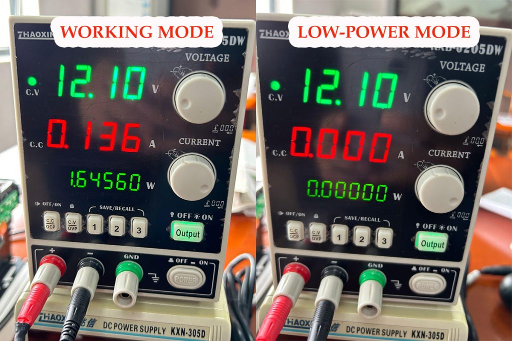
Power consumption is critical for outdoor field‑installed units. The radar level gauge supports sleep low‑power mode to reduce power draw.
⚠️ Important Note: Regular data query commands become invalid in low‑power sleep mode. The wake‑up exit command must be executed to switch back to normal mode before measurement data can be read.
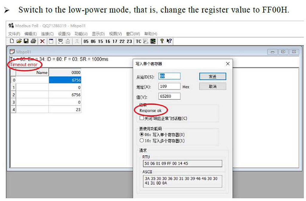
2.1 Enter Low‑Power Mode
Communication parameters: 9600 bps, RS485 bus
Host Send (OUT):
50 06 01 09 FF 00 14 45Sensor Reply (IN):
50 06 01 09 FF 00 14 45
The 5th and 6th bytes of the reply message are FF 00, signifying successful entry into low‑power sleep mode.
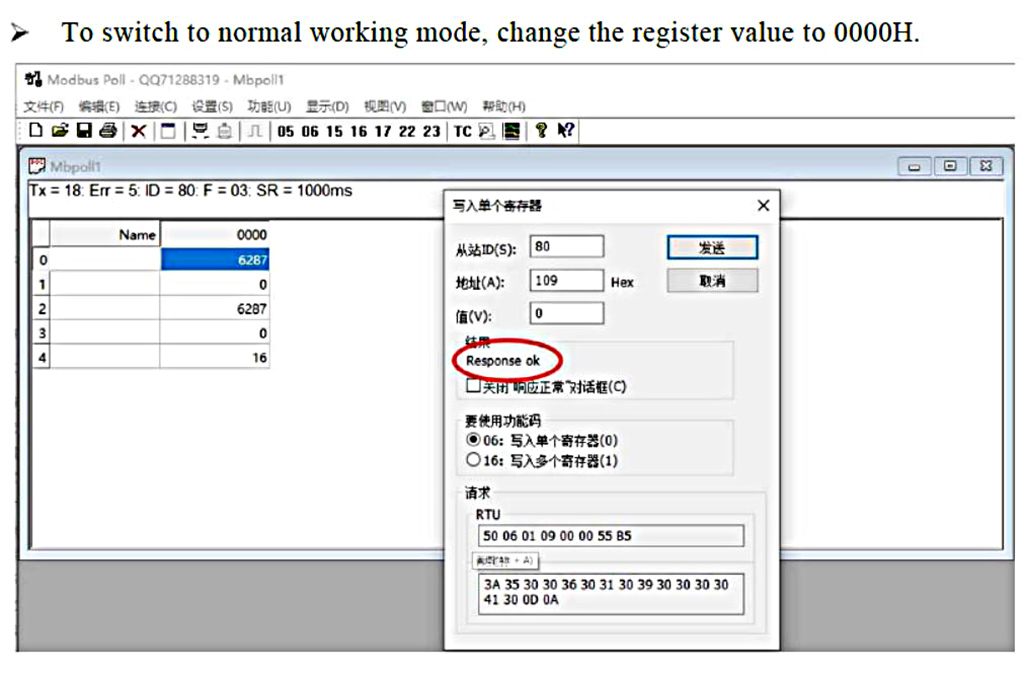
2.2 Exit Low‑Power Mode (Wake‑up Device)
Communication parameters: 9600 bps, RS485 bus
Host Send (OUT):
50 06 01 09 00 00 55 B5Sensor Reply (IN):
50 06 01 09 00 00 55 B5
The 5th and 6th bytes of the reply message are 00 00, indicating low‑power mode has been exited and normal operation restored.
After wake‑up completes, send the real‑time data query command to obtain level measurement results:
Host Send (OUT):
AA AA 00 02 02 00 00 00 00 00 00 00 55 55Sensor Reply (IN):
AA AA 00 04 82 01 01 0B 00 00 00 00 55 55
3. Modbus Protocol Configuration (Modbus Poll Host Software)
| Configuration Item | Value |
|---|---|
| Slave Address | 80 (Hex 50) |
| Function Code | 06 (Write Single Register) |
| Register Address | 109 |
| Write value 65280 | Enable low‑power mode |
| Write value 0 | Switch to normal operating mode |

H30 Water level meter Radar Modbus-RTU communication guide.pdf